none
900 - 1100
median of whole region
-30 - 30

cubic spline fit along column
-30 - 30
median of each row
-30 - 30

cubic spline fit along column
-50 - 50
C. W. Engelbracht; last updated 2004-7-2
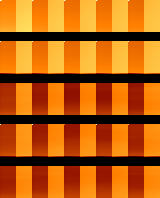
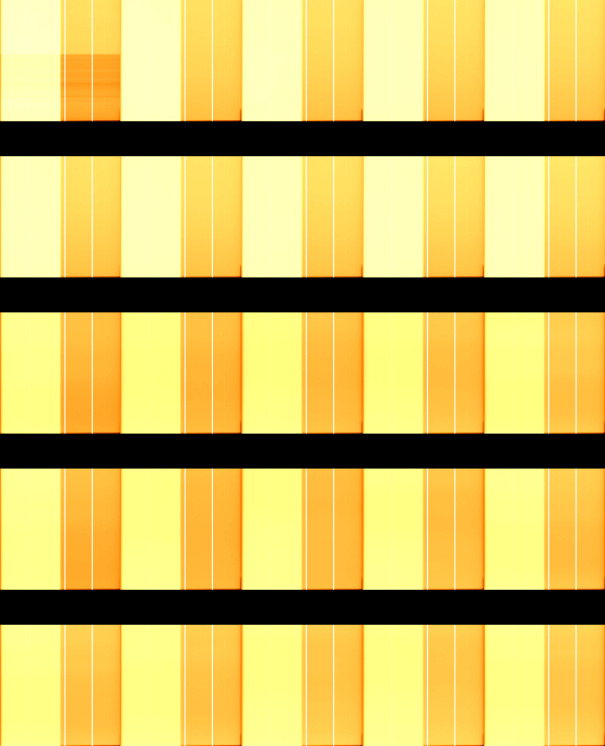
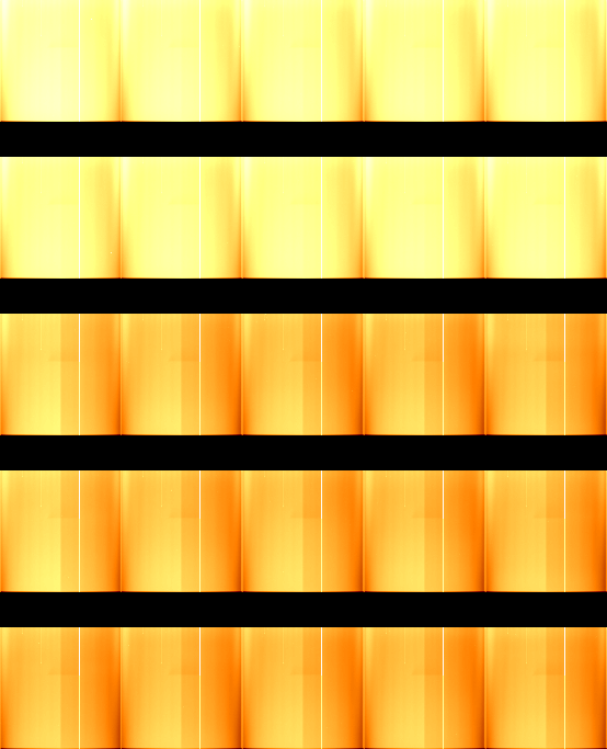
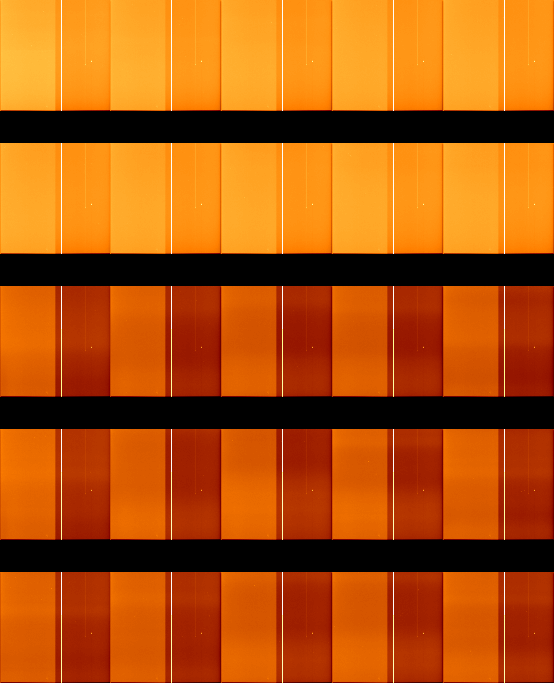
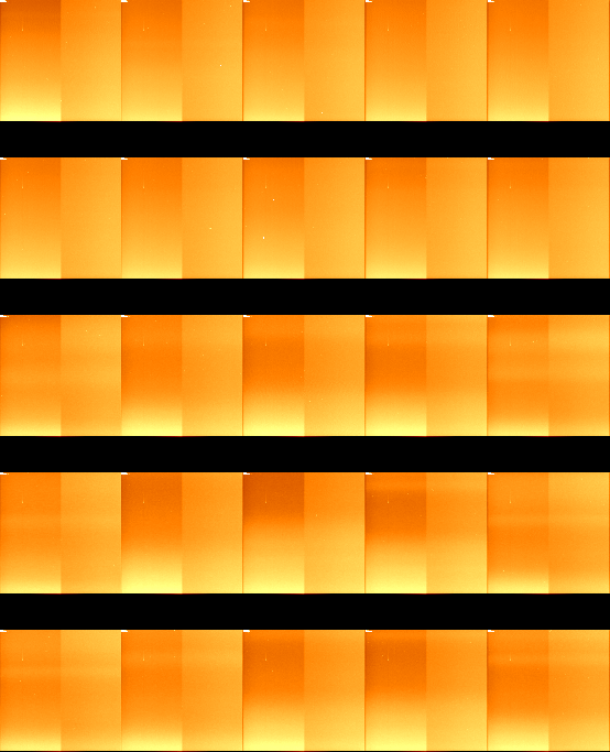
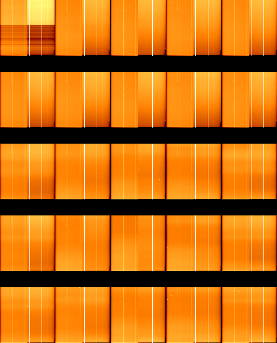
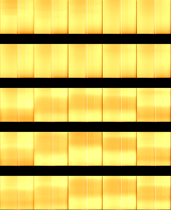
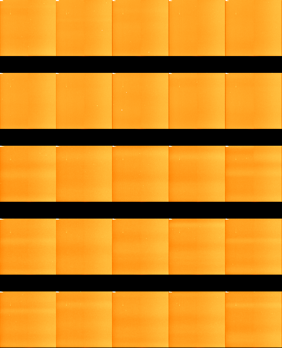
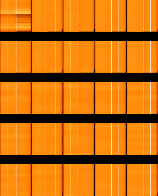
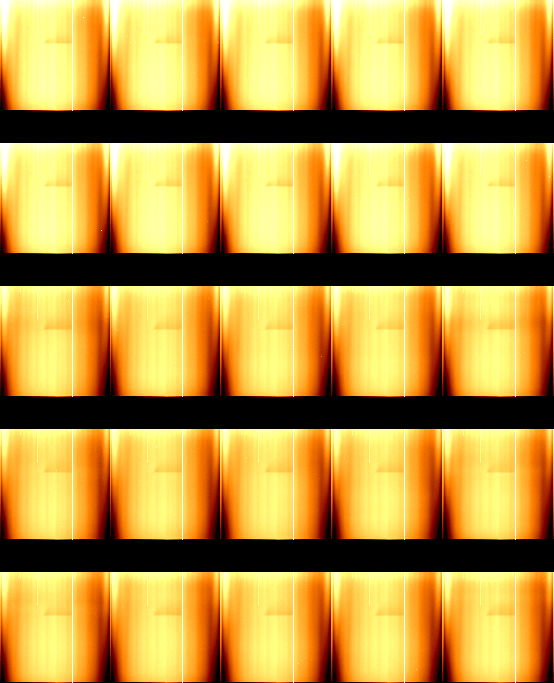
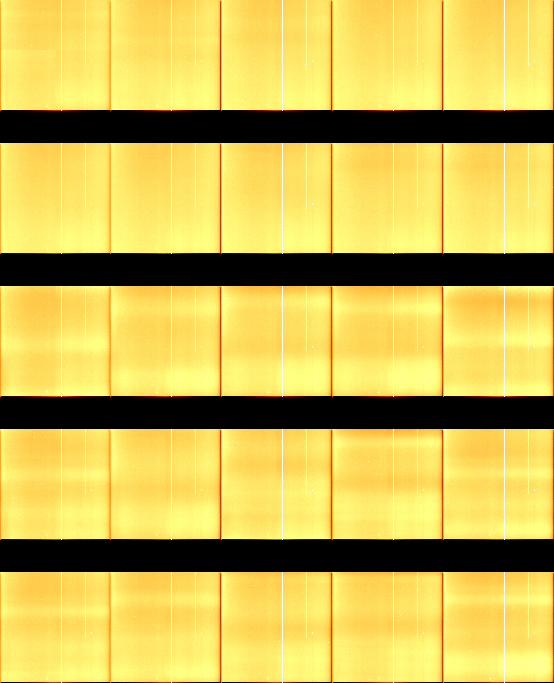
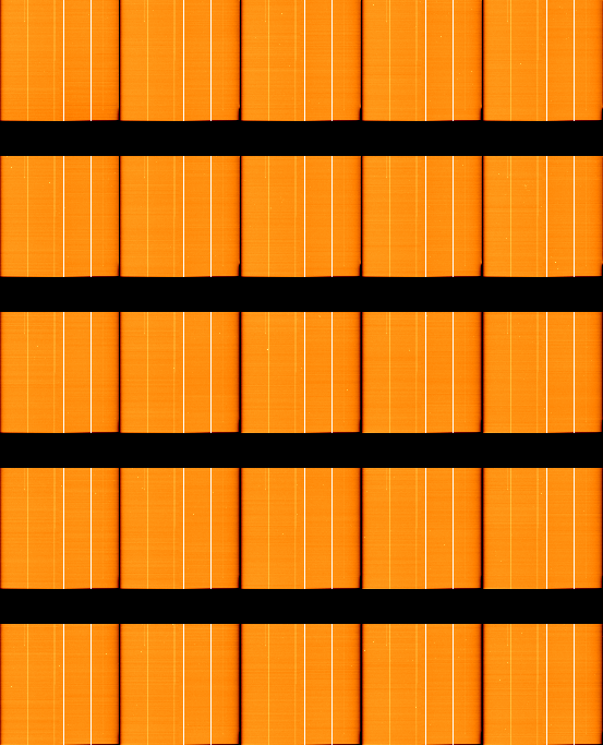
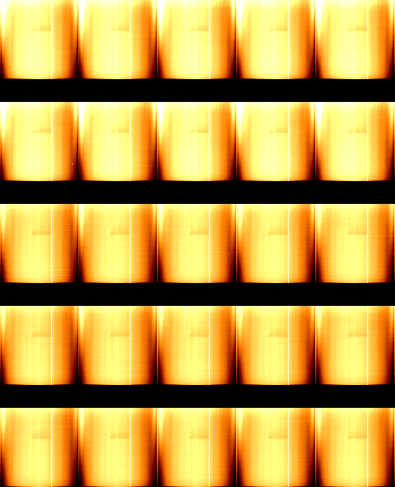
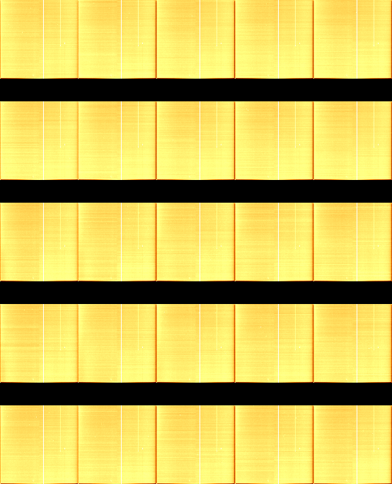
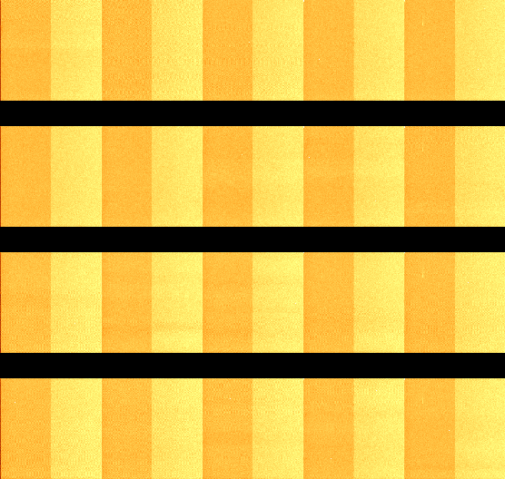
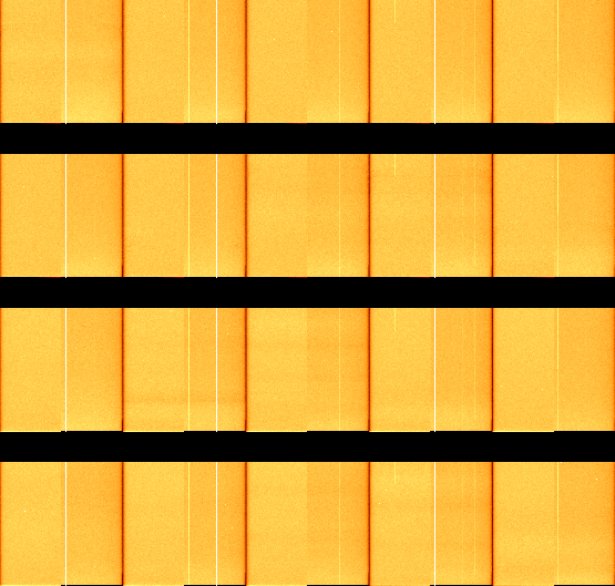
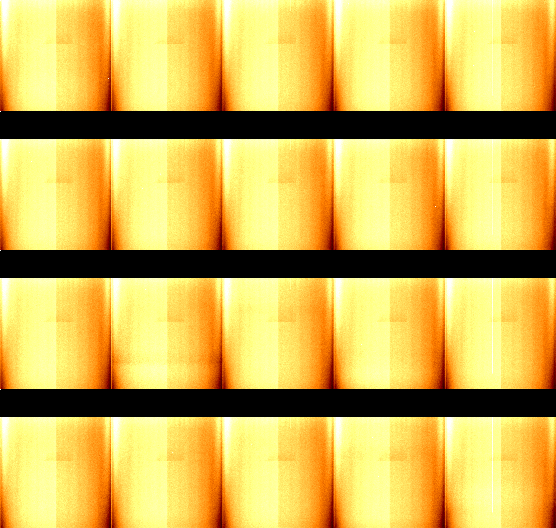
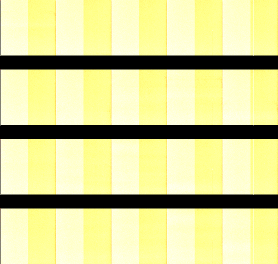
Each panel of the table below shows the 25 bias (zero) images obtained during the May 2004 90prime run or the 20 images obtained during the June 2004 run, one chip per panel as indicated along the top row. The top ten images in the May panels are from May 9, the middle 5 from May 10, and the bottom 10 from May 11. The top 10 images in the June panels are from June 20 while the bottom 10 are from June 21. The overscan subtraction method is summarized in the second column.
| Date | Overscan Subtraction Method | display range | Chip 1 | Chip 2 | Chip 3 | Chip 4 |
| May 2004 | none |
900 - 1100 |
|
|
|
|
| May 2004 | median of whole region |
-30 - 30 |
|
|
|
|
| May 2004 | cubic spline fit along column |
-30 - 30 |
|
|
|
|
| May 2004 | median of each row |
-30 - 30 |
|
|
|
|
| June 2004 | cubic spline fit along column |
-50 - 50 |
|
|
|
|
Figure 1

Figure 2
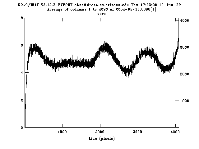
The final combined bias (zero) images are shown in Figure 3, with chips 3 and 4 on the top and chips 1 and 2 on the bottom. These images were created using a cubic spline fit to the overscan region and are plotted with the same display range of -50 to 50.
| Figure 3 | |
| May 2004 | June 2004 |
 |
 |